xxx
The 10788 is a PPS-4/1 display and keyboard controller. Its synopsis is described on the figure below.
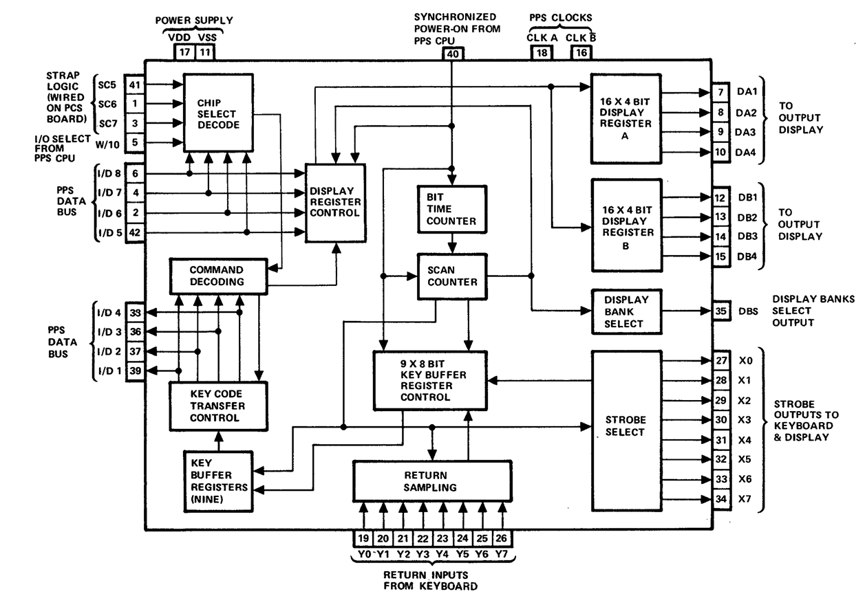
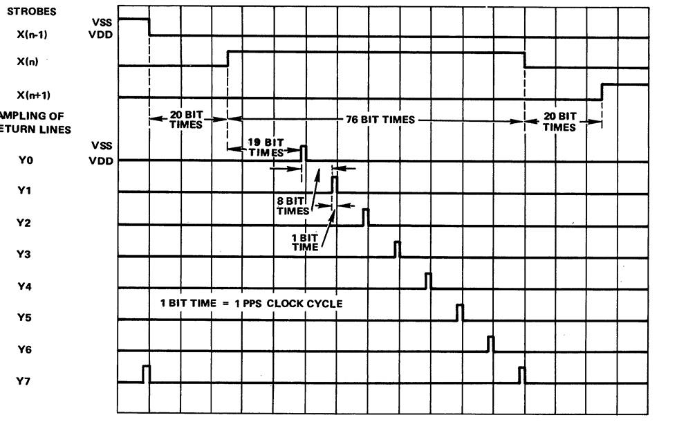
The 10788 provides 8 strobe lines (X) and 8 return lines (Y) to manage a matrix of 64 keys. The datasheet explains with many words how this switch matrix works. Actually, it is very simple and can be summed even more easily: If only one key is pressed during a scan cycle, this key is stored in a 9-key buffer. if many keys are depressed at the same time (during a scan cycle) all the events are simply ignored. The duration of a scan cycle is: 8 strobesx96 bit time x 2 = 1536 bit time, which is about 7,68ms. The x2 comes from the fact that X strobes are sequentially activated from 0 to 7 with DBS=0, then again with DBS=1. DBS is used for the display mux. The key scan is actually performed during DBS=1. One can see that by looking at the last line of the figure below “Return sampling”:
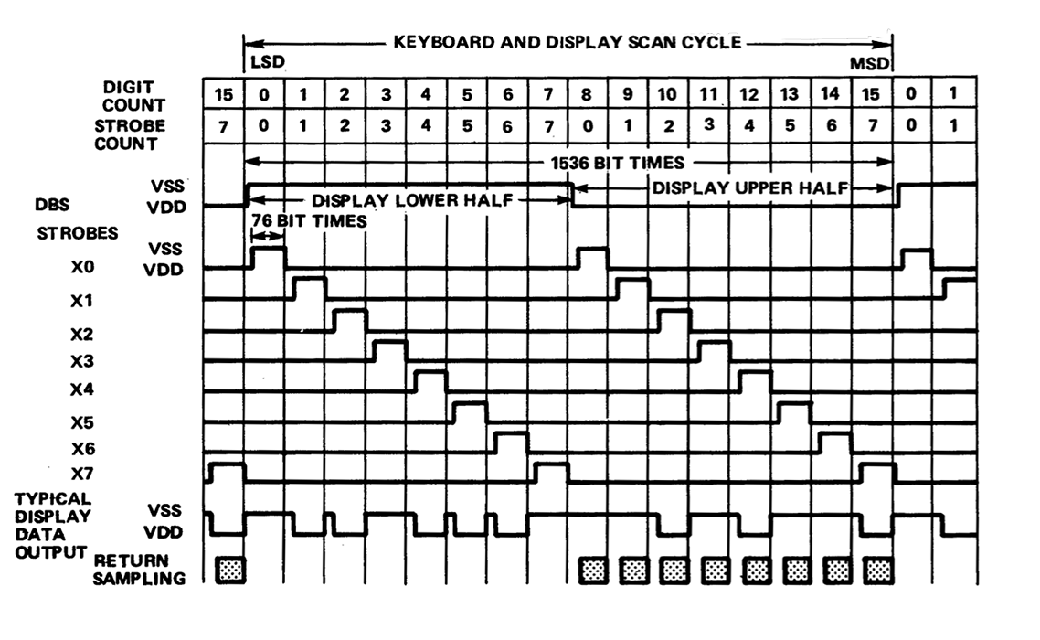
The 10788 provides 8 strobe lines (X) and 8 return lines (Y) to manage a matrix of 64 keys. The datasheet explains with many words how this switch matrix works. Actually, it is very simple: If only one key is pressed during a scan cycle, this keys is stored in a 9 keys buffer. if many keys are depressed at the same time (during a scan cycle) all the events are simply ignored. The duration of a scan cycle is: 8 strobesx96 bit time x 2 = 1536 bit time, which is about 7,68ms.
Chip selection of these circuits is possible by the use of 3 chip address straps that can be terminated, by the user, to create each chip address. The GPKD is then selected when SC5, SC6, SC7 = I/D5, I/D6, I/D7 and I/D8 = 1b. The GPKD is accessed with an I/O enable signal from the CPU and a simultaneous 8-bit instruction from ROM. 4 bits of the instruction are used to address the particular GPKD chip (I/D5..8 is the device ID); the other 4 bits define the I/O operation (I/D1..4 is the command).
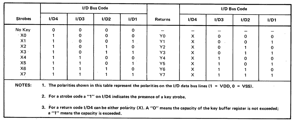
The 4-bit operation code is interpreted by the GPKD with respect to the table presented below:
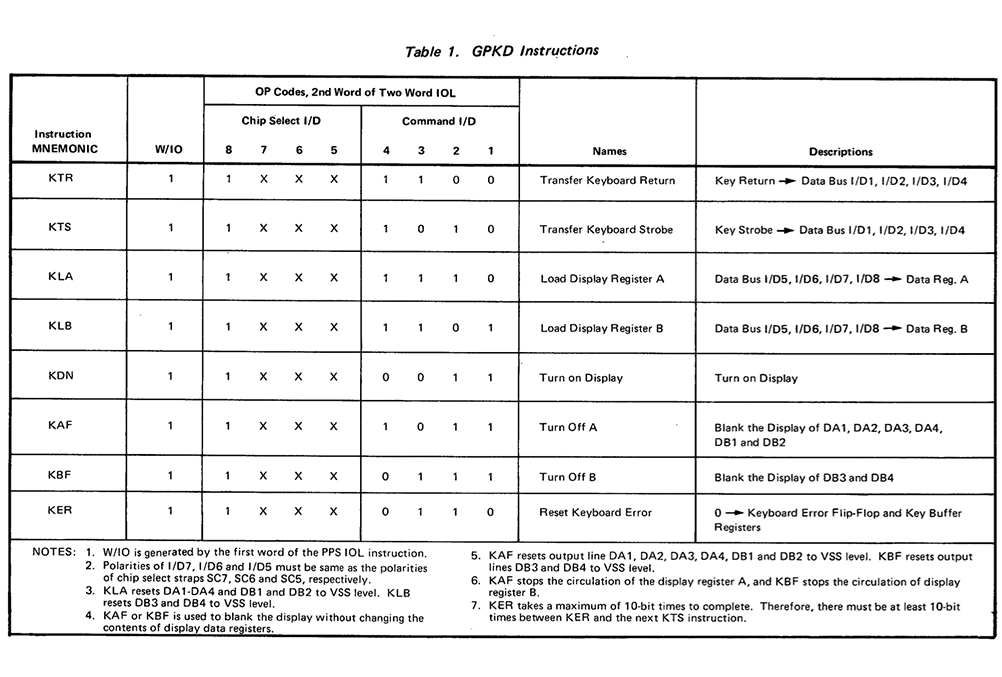
When a key press is detected, its code (#strobe, #return) is added to the internal buffer of the 10788. The CPU has access to this buffer by sending a KTS command. The bit 3 of the returned code will determine if there is a key pressed available from the buffer. If yes, then a KTR command will give the second part of the key code, and unstack the key from the buffer. In the end, you have the key codes of the strobe and return that were detected for this key press. Besides, this encoding explains why the 10788 only handles one key stroke at a time (because otherwise, one cannot send multi codes to the CPU in only one set of 2x4-bit).