xxx
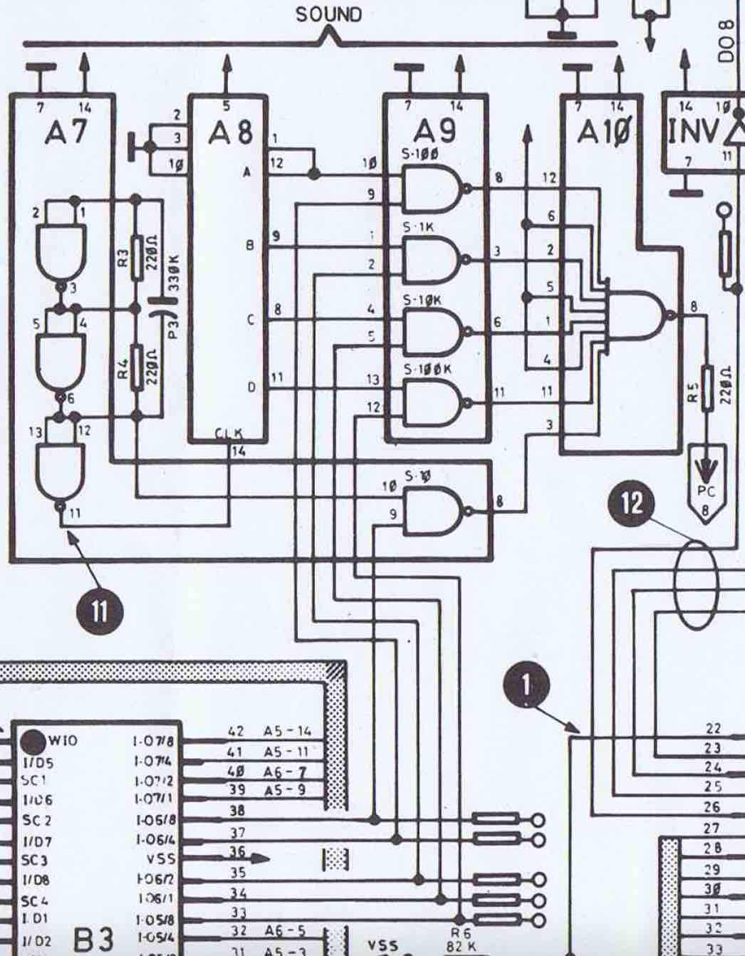
The sound subsection is described above. A7 is mounted as a multivibrator at frequency F0. It serves as an input for A8 (SN7493) which is a double binary counter, configured as a 4-bit BCD counter.
From A8, we then get 4 square signals at F0/2, F0/4, F0/8, F0/16. Plus F0 which is directly picked from A7. Every signal is gated by its own strobe signal through the 4 NAND of A9 (plus the last available NAND of A7). The 5 strobes are generated by the PIO 11696.
A10 (SN7430, octuple NAND) is eventually used to anding the 5 signals and generates Sound-out.
Base frequency F0, is hard to determine. On the Recel schematics, it looks like the signal is meant to be a 25KHz square signal. But it is not the real value that can be measured at A7 pin 11: Around 6KHz. This value may vary from one 7400 to another. Using an incompatible technology (such as LS for example) may lead to a different frequency, or even could not oscillate at all.
Following the original design, we just have to synthetize a clock and a 4-frequency divider. In the end, we combine the 5 tone to genrate the sound out output. File gentones.vhd reflects this logic in VHDL. See on Github Here